|
POWEROLL Drive for Traversing Sampler |
|
|
 |
|
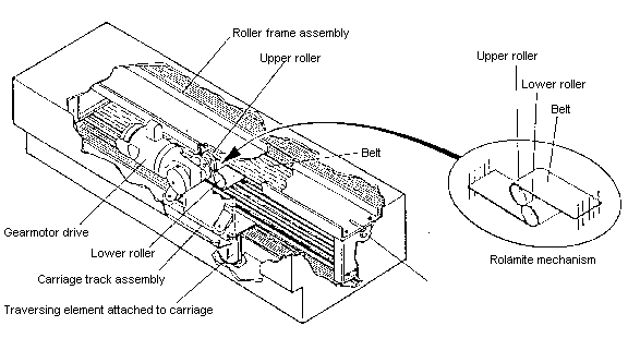
The PWR traversing drive for linear sampling is applicable to slurry and solids streams, employing the high mechanical strength powerolltm principle. The PWR design with belt drive through a dual pulley mechanism from a gearmotor assures linearity of cutter traversing motion at controlled constant speed. Reliability of sample is thereby maintained to metallurgical requirements with typical cutter traversing constant speeds of 18 inches per second (0.46 meters per second) or other specified speeds according to standards. The PWR unique mechanical design with its inherent rugged construction leads to low maintenance with superior operational reliabilty. The Poweroll drive roller action is essentially frictionless, and the mechanism requires no lubrication except for bearings mounted on roller axles on the carriage. Carriage wheels are offered with sealed life-lubricated bearings. Cutters furnished with the PWR sampler mechanism meet operational requirements and can be selected from "A" (vertical blade) and "B" (horizontal) configurations for solids and slurry sampling applications. For sampling solids, bottom dump, pivoted spoon or other cutter configurations are provided to meet standards of sampling accuracy as applicable to the installation. Cutter specifications for either solids and slurries are always set out according to the purchaser's application. The powerolltm PWR drive mechanism for sampling is suitable for continuous operation, and can be used in applications such as slurry sampling for on-stream analyzers. The PWR mechanism can be furnished for strokes from 16 inches (400 mm) up to 200 inches (5000 mm.) or greater. No loss of mechanical stability or linearity of motion occurs through the maximum stroke length. This is achieved through the unique powerolltm transmission to translate constant speed rotary motion from the gear reducer motor to linear traversing motion. The simple, high strength construction enables shock and sudden stress loads on the mechanism to be damped through the powerolltm belt and roller drive system. The drive motor can be specified for 110/220 VAC 50/60 Hz single phase for 1/2 to 3 HP drive or greater, with 360/460 50/60 Hz three phase power. Other electrical requirements can be met according to purchaser's specifications. Timer control units are separately offered. |
|
[Home] [Company Info] [Products] [Installations] [Theory] [Analyzers] [Contact Us] |
|
© 1997, Harrison R. Cooper Systems, All Rights Reserved |